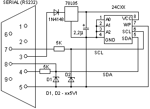
- #Diy eeprom programmer serial
- #Diy eeprom programmer full
- #Diy eeprom programmer software
- #Diy eeprom programmer code
Pdmtr's PCB Tips - Posted by: Jeff Frohwein Mike's PCB Tips - Posted by: Jeff Frohwein Using the Positive Proof Photo-etching system. Ian Juby's PCB Tips - Posted by: Jeff Frohwein Caveats: schematics are limited to one sheet and boards to 100 x 80 mm and two sided. The Eagle layout system comes with schematic capture, parts editor, PCB layout, and autorouter.
#Diy eeprom programmer software
Great schematic capture and PCB layout software can be had from. Free PCB Layout Software - Posted by: Claude Ceccon PCB etch tips, RF prototyping with copper tape, cheap RF remote control. PCBEtch - Easy PC Boards - Posted by: Jeff Frohwein Used with a PC it can implement a dual channel 100 Mhz Digital Sampling Oscilloscope and 8 channel Logic Analyzer. The whole things fits on one single sided PCB with virtually no wiring.īitScope is a low cost data acquistion device configured as an RS-232 perhiperal. Internal triggering is fully maskable (High/Low/Don't Care) on all 32 channels. It is a 32 Channel, 40Mhz, fully PC controlled TTL/CMOS logic analyser with internal/external triggering and trigger delay. Measurement - 40Mhz 32 Channels Logic Analyzer - Posted by: Jeff Frohwein TOO MANY REQUESTS ARE RECEIVED TO ANSWER THEM ALL. DO NOT ASK FOR HELP GETTING IT TO WORK OR FOR MORE INFO.
#Diy eeprom programmer code
This is the software & C source code for Dos. Here's a 27C040 (512k byte) eprom emulator circuit and a 27C256 (32k Byte) version. I'll push it out once I finish fixing my soldering job and getting a valid ROM write."News & info related to do-it-yourself electronic tools."Įprom Emulators - 4Mbit Eprom Emulator - Posted by: Jeff Frohwein I suspect a race condition, but now I spin on a reread until I get a valid data chunk.
#Diy eeprom programmer serial
It also handles some weirdness with the serial pipe that was causing the "OK" reply to come later than expected sometimes. I rewrote it to be a bit cleaner, if perhaps a bit slower. That's a note for myself.Īnyway, I'll push the new code tonight. So, always recheck every bit of soldering you do. Sure enough, a minute of checking later, and there is continuity between address pins 8 & 9. And it would have to involve pin 8 (because it was breaking at decimal 256, the number of addresses capable of being represented in 8 bits). Now, it could only be one more thing: I had to have bridged two pins together when soldering on the pin headers. What if this whole time, I was chasing a hardware bug? I looked at the pin definitions. And, watching the output of compare scroll by, it was obvious that it was entire chunks of data that were wrong.Īnd I think that was about when the light began to dawn.Īfter having hacked at the arduino firmware and my python script for hours, it suddenly occurred to me that I was likely seeing a byte written later overwriting the original.
#Diy eeprom programmer full
Using the serial interface in the arduino IDE, I could read and write to location 0x100.īut a full write still fucked up. So, now I add some elaborate and slow checks on the write process. I should have figured it out from that, but I'm slow. That's the hexadecimal form of the number 256.

It consistently wrote the wrong data to location 0x100. Reburn.Īnd now I had the location nailed down.


Oh, ok, maybe something happened and it didn't write out correctly. So, after getting some very weird results from running Andre's test ROM v2 in my Gorgar, I decided to go and write that compare function that I had glossed over in the first place.


 0 kommentar(er)
